
Independent CFD
On-Board Scour versus conventional bottom plenum
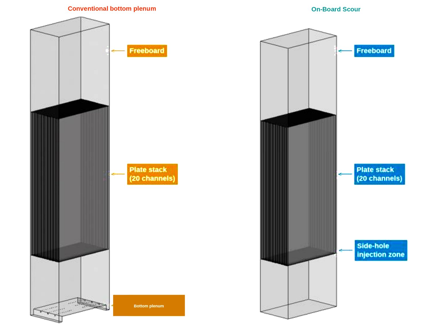
On-Board Scour keeps uniform water velocity between each plate. A conventional bottom plenum shares one chamber under the stack and lets buoyancy sort the rest. Independent CFD stills of the two on identical plates.
Hydrodynamics only — fouling, flux, biology, and long-term operation are outside the scope. These are independent CFD predictions under the stated modeling assumptions. They are not plant data.
The CFD was run on a 20-channel section. The shipped module is 130 plates (single-deck, ≈136.5 m2) or 260 plates (double-deck, ≈273 m2). Figures of 20 panels, ≈21 m2, and 200 L/min described that modeled section only.

What the study compared
| Conventional | Three-header bottom-plenum air scour. Shared chamber under the stack. |
|---|---|
| Zyramic On-Board Scour | Direct injection at the base of each channel. No bottom plenum. |
| Modeled section | 20 channels (not the shipped module). Plate 1,047 × 502 × 7.60 mm, 6.40 mm channel gap. Identical in both cases. |
| Domain | Bi-symmetric quarter-domain. About ten of twenty channels genuinely resolved. |
The conventional case is a conventional-style geometry on Zyramic’s own plate. It is not a named competitor’s product.
Where scouring begins
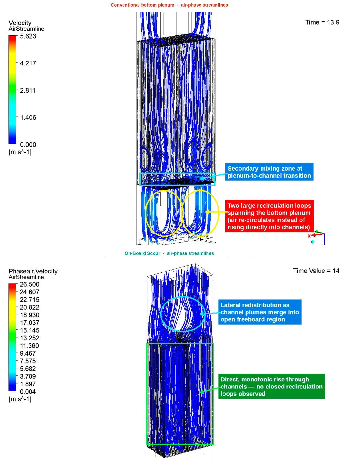
Near-field water velocity at the channel base — the liquid shear where scouring starts — was 2.4–2.6 m/s with On-Board Scour versus 0.5–0.75 m/s in the bottom plenum. That is about four times the liquid shear at that location. It is not a claim of four-times scouring over the whole panel. In-channel peaks farther up the plate are similar in both designs, on the order of 0.7–0.9 m/s.
Direct rise through every channel
Channel to channel
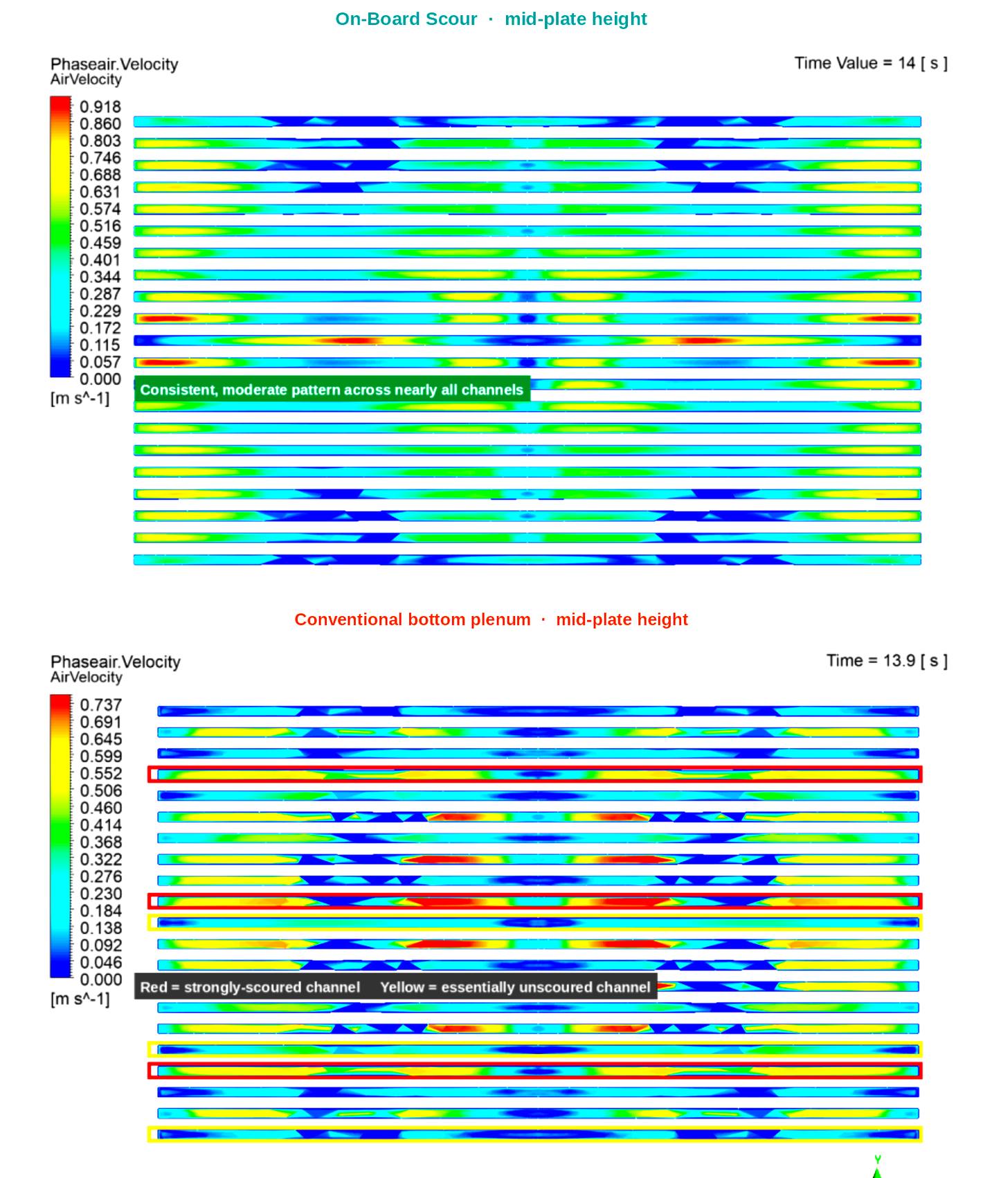
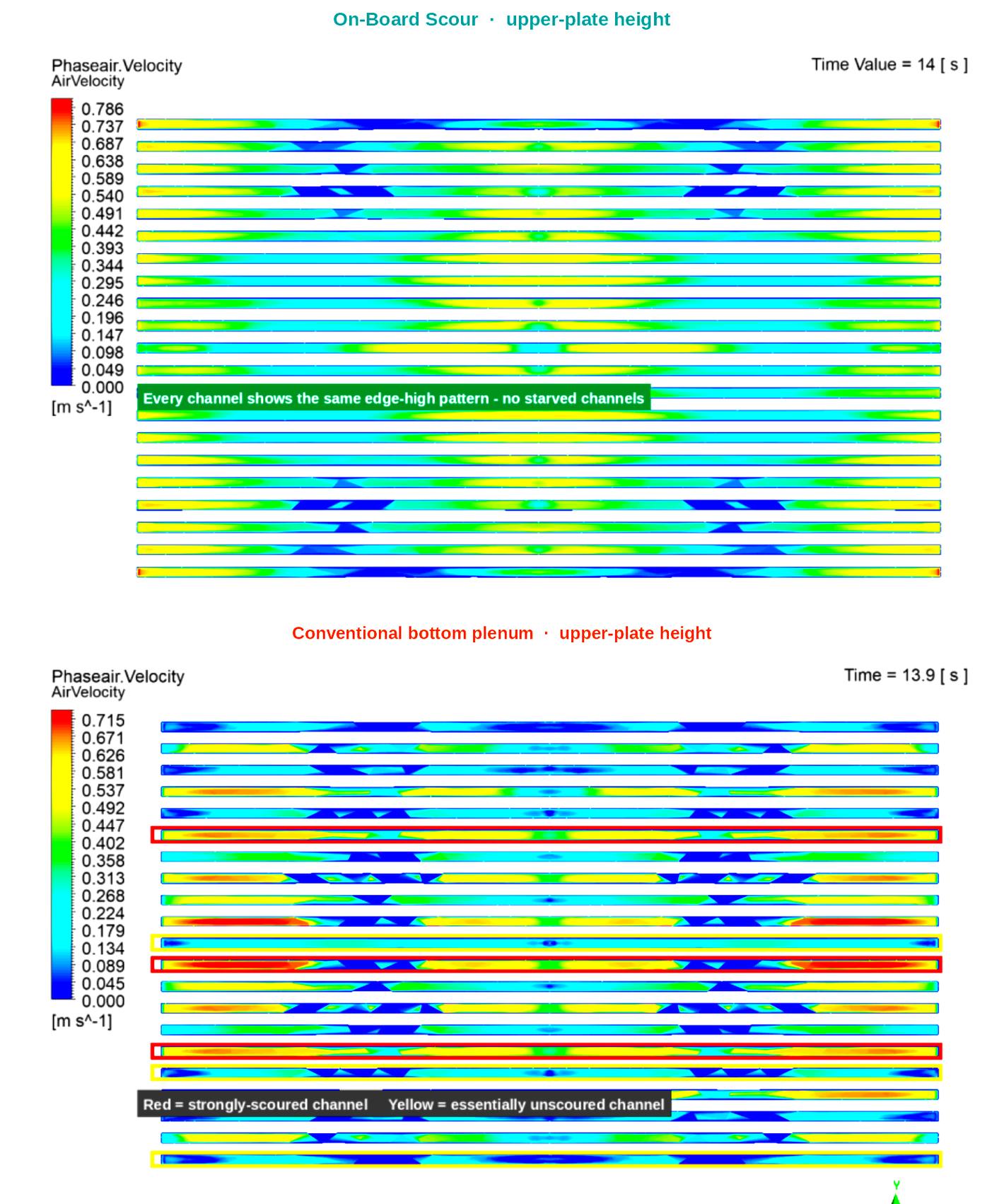
Same cross-section, two heights. The mid-plate and upper-plate heat maps look down the identical channel array. On-Board Scour stays even in every channel at both heights. The conventional bottom plenum shows strongly-scoured channels next to starved ones, and that mix persists toward the top of the panel.
The uniformity finding and the near-field shear finding are separate. Together they show even scour in every channel, and a strong start at the plate base.
Shared limits, not differentiators
- Both designs show an edge-high, centre-low pattern across the 502 mm panel width (riser/downcomer in the enclosed channel).
- Both show decay of scouring velocity over the upper portion of the 1,047 mm panel. Zyramic’s response is a shorter panel, not a claim that the decay is absent.
What this study does not show
- Lower fouling, higher flux, longer membrane life, or less blower energy in the field.
- Physical or plant validation. None has been done against this model.
- Full-rack header or manifold asymmetry. The quarter-domain cannot confirm it.
Datasheet, O&M, and warranty are on Downloads.